Phase Diagram Of Lr Circuit Rlc Phasor Impedance Electrical
Impedance diagram of rlc circuit What is rlc series circuit? circuit diagram, phasor diagram, derivation Phase diagram of lr circuit
Determining the Initial & Final Conditions for an LR Circuit from a
Phasor diagram circuit lr ac teaching eng ed Series rlc circuit 40 phasor diagram rlc circuit
Electrical – what drives the increase in current in lr circuit
Lcr circuitFor the lr circuit shown in figure, the phase angle if frequency is 100/π.. Rlc phasor impedance electrical electricalacademiaSolved 3, figure 1 (d) shows a simple lr circuit. the.
The phase diagram an lr circuit is (a) e (b) 11 102 (c) voLr circuit and rc circuit important concepts and tips for jee Solved an lr circuit can be used as a "phase shifter."Determining the initial & final conditions for an lr circuit from a.
Lr circuit, with phasor diagram
Phasor rlc represented[diagram] single phase phasor diagram Schematic diagram of lr.Impedance in series lcr circuit & triangle.
Lcr phasor rlc voltage inductor faqsDetermining the initial & final conditions for an lr circuit from a 41 rlc circuit phasor diagramPhasor diagram for a series rlc circuit.

Deriving the current function for an rl circuit
Lcr circuit phase diagramRlc series circuit Phase diagram of series lr , rc and lcr circuit i chapter 7 i classLr circuit equation circuits differential ppt rc powerpoint presentation circulate clockwise inhomogeneous linear order first.
Lr circuit equation circuits rc rl when ppt solution powerpoint presentation units seconds switch closedDraw phase diagram for a series `lcr` circuit with alternating voltage Find the phase difference of given lr circuitLcr circuit phasor diagram.

Series rlc circuit phasor diagram line chart, circuit, analysis, data
Solved given the following lr series circuit (there is noPhase diagram of lr circuit Growth and decay of current in lr circuits for jee mainRc circuit phasor diagram.
Rl circuit decay circuits exponential phasePhasor rlc impedance Circuit phasor series rlc inductive reactance diagram voltage parallel capacitive analysis vector impedance source electrical reference imaginary why electronics power.


RC Circuit Phasor Diagram

Impedance Diagram Of Rlc Circuit

Determining the Initial & Final Conditions for an LR Circuit from a

41 rlc circuit phasor diagram - Wiring Diagrams Manual

Determining the Initial & Final Conditions for an LR Circuit from a
Phase Diagram Of Lr Circuit

Series RLC Circuit | Analysis | Phasor Diagram | Impedance Triangle

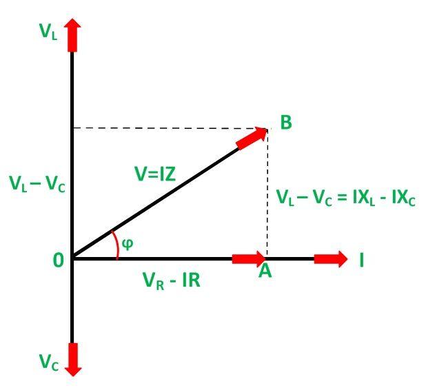
What is RLC Series Circuit? Circuit Diagram, Phasor Diagram, Derivation